HUGHES MAGNETIC BALANCE
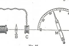
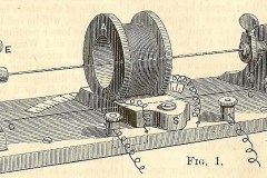
The Hughes “Magnetic Balance” was used to measure the magnetic properties of iron and steel. The measurement was not made in absolute units such as Tesla (modern unit) but by degrees as read off the protractor scale. Measurements were relative and for comparison with one material vs. another. The original device was invented by Hughes in the early 1880’s before units of measurement for many electrical parameters were standardized.
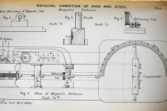
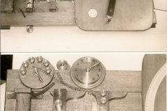
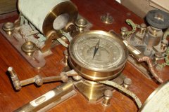
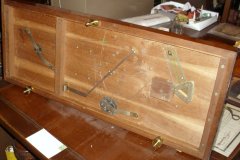
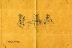
A copy of Hughes description is provided in “Description of Apparatus” from a paper titled “Physical Conditions of Iron and Steel”, Jan 1884. The first set of photographs are of apparatus in the science Museum, London. The version shown was constructed for him by the instrument maker “Groves” of London. Hughes did not patent this instrument but gave it away freely.
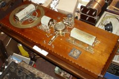
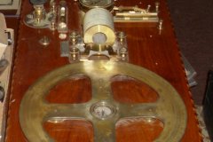
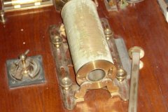
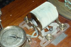
The second sets of photographs are of an instrument in the Grays Wireless Museum Mason Ohio and are provided by permission of Bob Theatere. This has a slightly different configuration and a description of this instrument is provided below.
Later Version of the Hughes Magnetic Balance, Grays Wireless Museum Mason Ohio
This unit was probably a later development and differs in its configuration from Hughes’s original configuration; however the principle of measurement is the same. The main difference is rather than using an electromagnet that could be rotated Hughes used a fixed magnet. that could be rotated. He used a suspended magnetic needle as the detector vs. this unit that uses a magnetic compass.
Principal of operation: First the whole unit was leveled and orientated basically east/west and further adjusted until the magnetic compass needle was pointing at right angles to the coil axis. This was basically rendering the unit astatic and removing the magnetic influence of the earth’s magnetic field. Next the rotating electromagnet was excited with a DC current. None of the other coils were excited (we will come back to this later).
Next a magnet whose strength or properties were to be measured in the form of a piece of wire, bar or plate was placed on the tray and slid into the coil up against the fixed stops (this we will call the test magnet). This ensured the test piece magnet was always a set distance from the compass. The compass needle would be influenced by this magnet and thus be deflected to the left or right depending on the polarity. Next the rotating electromagnet would be rotated so its magnetic field (of opposite polarity) would push the compass needle back to its zero position i.e. null out the effect of the test magnet. The degrees of rotation would then be read off the scale. The test magnet would then be turned around so that the polarities were reversed and the test redone. This was to eliminate the effects of stray or earth magnetic effects. The readings would be averaged (neglecting the sign). Thus it can be seen that using standard dimensioned test pieces of different metals a comparison can be made of their relative magnetic strengths. To accommodate a wide range of materials and magnetic strengths the voltage to the electromagnet could be adjusted usually by a series of fixed resistors to set it up for the series of tests.
To test soft iron properties (a material used as a core in electromagnets to increase its magnetic strength, but itself was not a permanent magnet) it was necessary to insert it into the coil and energized it to create an electromagnet. The set up was as above but in this case the test piece was now inside an energized coil. Again the excitation current could be adjusted. In this set up however there are two magnetic effects created. One by the coil and a second one by the coil when it has a test piece inserted in it. As it is desired to only measure the effect from the soft iron test piece it is necessary to first negate the magnetic effect of the coil itself. This is where the third shorter coil comes into play.
This is done as follows: the electromagnet is energized by a DC current. (The coil at this stage does not have the test piece inserted). This will create a magnetic field and cause the compass needle to rotate. The third coil is energized with a DC current but of opposing polarity so that it drives the compass needle back to its null position. The test material is then inserted into the coil and the stronger magnetic field now created will rotate the compass needle. The rotating electromagnet is rotate until it restores the compass needle back to its null position and the degrees read off the scale.

